
3D IPC-2581 Viewer
The free part of the freemium.
ZofzPCB supports IPC-2581B
The format contains everything a Gerber File Set does, like images for all layers, drills, netlist, BOM, and Stack. The information inside the IPC-2581 is strictly structured. Usually, there is no need to add anything to fully and automatically define/understand the PCB and assembled components.
Thanks to the included geometry data and netlist (the equivalent of IPC-356), ZofzPCB can create component models right from the start.
Currently, any additional settings, especially the components adjustments, are saved only as .zofzproj binary file. That means you need to repeat the settings for the next PCB revision.
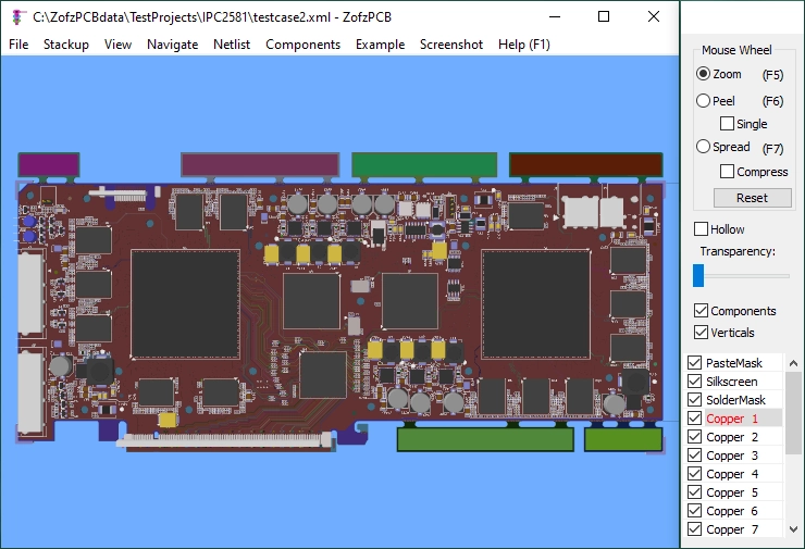
Image of "Testcase2.xml" - the file provided by the consortium for testing purposes:
Stackup
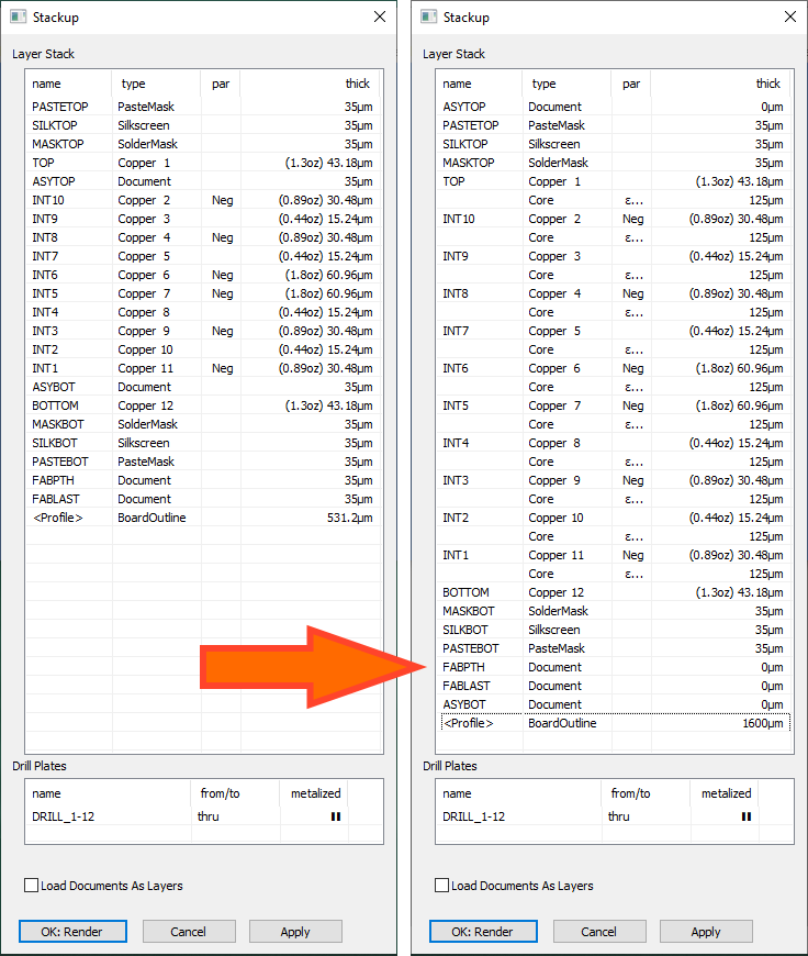
Most of the IPC-2581 files describe only logical stackup information. For example, if mechanical (thickness) information is inadequate, it might be needed to edit the thickness column in the stackup. Note - when you specify the total board thickness, using the <Profile> layer thickness entry, all missing core layers will be created automatically.

Drawing Edges
In IPC-2581, the board shape is represented by a face, not a drawing of face edges. This approach is an excellent improvement from the unclear Gerber semantics. However, rare elements on the drill layers could still be represented as a drawing. ZofzPCB detects and converts such objects. In the case of repeating the board outline edges in a drill layer, the drawing is removed, as it would cause a cutout of the shape of the PCB in the PCB, rendering the board shape empty.
Forum
Please report problems at the forum Bugs ➔ IPC-2581
For more information about the IPC-2581 standard, please go to IPC-2581 website.