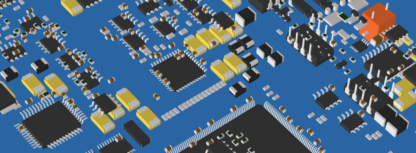

3D Components Modeler & Body Builder
Components Modeler - Free
This feature is needed for the new M&MS functionality. As the M&MS needs to be free, we have moved the 3D Components Modeler to the free version.
Body Builder - Premium
Components List - text file
What is a IPC-356 File?
IPC-356 is an electrical test file for a bare PCB (by original purpose) and contains a list of points to test, defined by:
- The netlist node name.
- Component ID and pin ID or, instead, the label "VIA".
- The geometrical location, defined by x,y coordinates, and accessibility code (top, bottom, both).
- A simplified description of the point shape: round (diameter, hole diameter) or rectangular (size, rotation).
- In the newer "B" version, test point geometry might be composed of several basic shapes.
The test points are located on THT and SMD pads. Not tented vias may also be included, of course, without the component and pin identification.
Points having the same netlist name are supposed to be electrically connected.
The IPC-356 file is a popular export option, available from virtually all ECAD packages, along with P&P , BOM, drill, and layer Gerbers.
So, what can ZofzPCB do with it?
- Netlist check, as with the actual bare PCB, the 3d PCB model can be tested. At the same time, internal copper netlist nodes can be named by names from the IPC-356 file.
- Display every test point text data when you place the mouse pointer on it. Every SMD pad and THT hole is named by component ID and pad ID.
- Display the test points - IPC-356 contains 2D geometry of the access point: round (diameter), rectangular (width, length, rotation).
- It is possible to group the test-points by component designator ID. The result is a pin-out image for each component's footprint. This is the base for the component shape modeler.
Adopting the IPC-356 File
The first approach, not available anymore, was just boxes symbols for the test points. Together with the mouse hover info display, it was precisely representing the IPC-356 file content. The following screenshot could be an IPC-356 file definition:
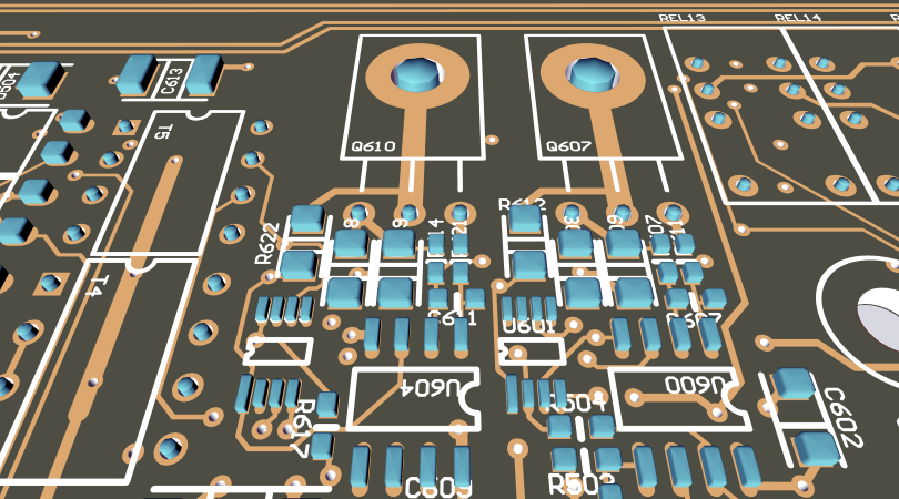
The Components "Extruder"
The next step was to group test points by component ID, adding an extra box representing the component body. The trick is to determine the component box size, color, rotation, and position. The body shape also depends on the designator's text, in some cases. This functionality is available in the current software versions. The component model is called "extruded".
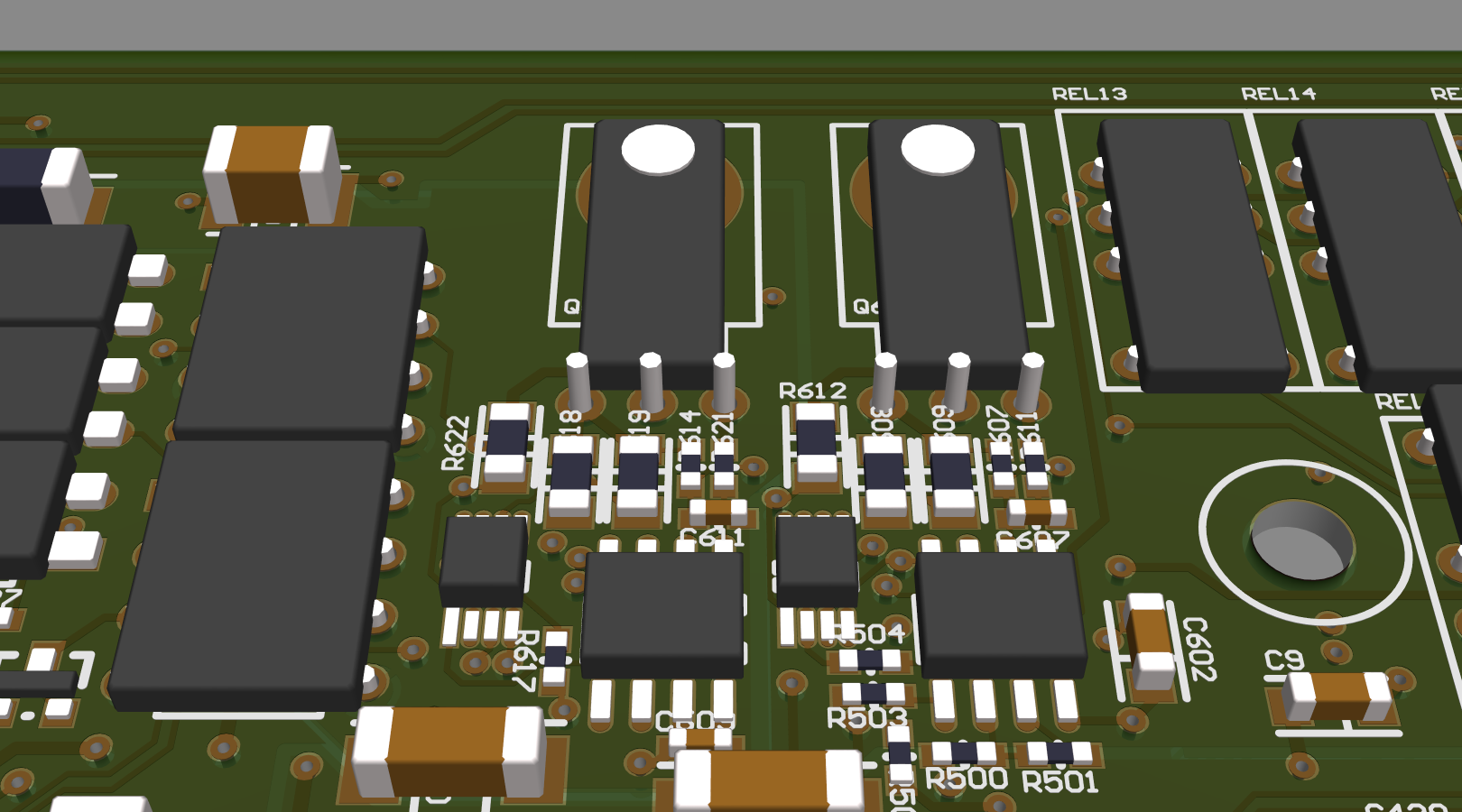
The role of this Component Modeler is to provide mouse pointer targets for components and pin browsing if you do not wish to obtain the actual Component Modeler license. Also, it serves cases where the parametric Component Modeler fails.
Parametric Components Modeler
First, footprint geometry is classified on various aspects: number of pins, SMD/THT, number of rows, heat sink pad, etc... Then, there are components tables for each particular component class. Finally, component tables have various abstraction levels. For example, QFPs are fixed, but SO allows for variable pin numbers. Even more versatile are 2-pin THT resistors - all dimensions are adjustable to fit in the PCB holes automatically.
Unfortunately, at the moment, not all component case variations are present in the tables. Therefore I am thinking of moving the tables outside of the program as readable CSV files, making it possible to upgrade independently also by the user.
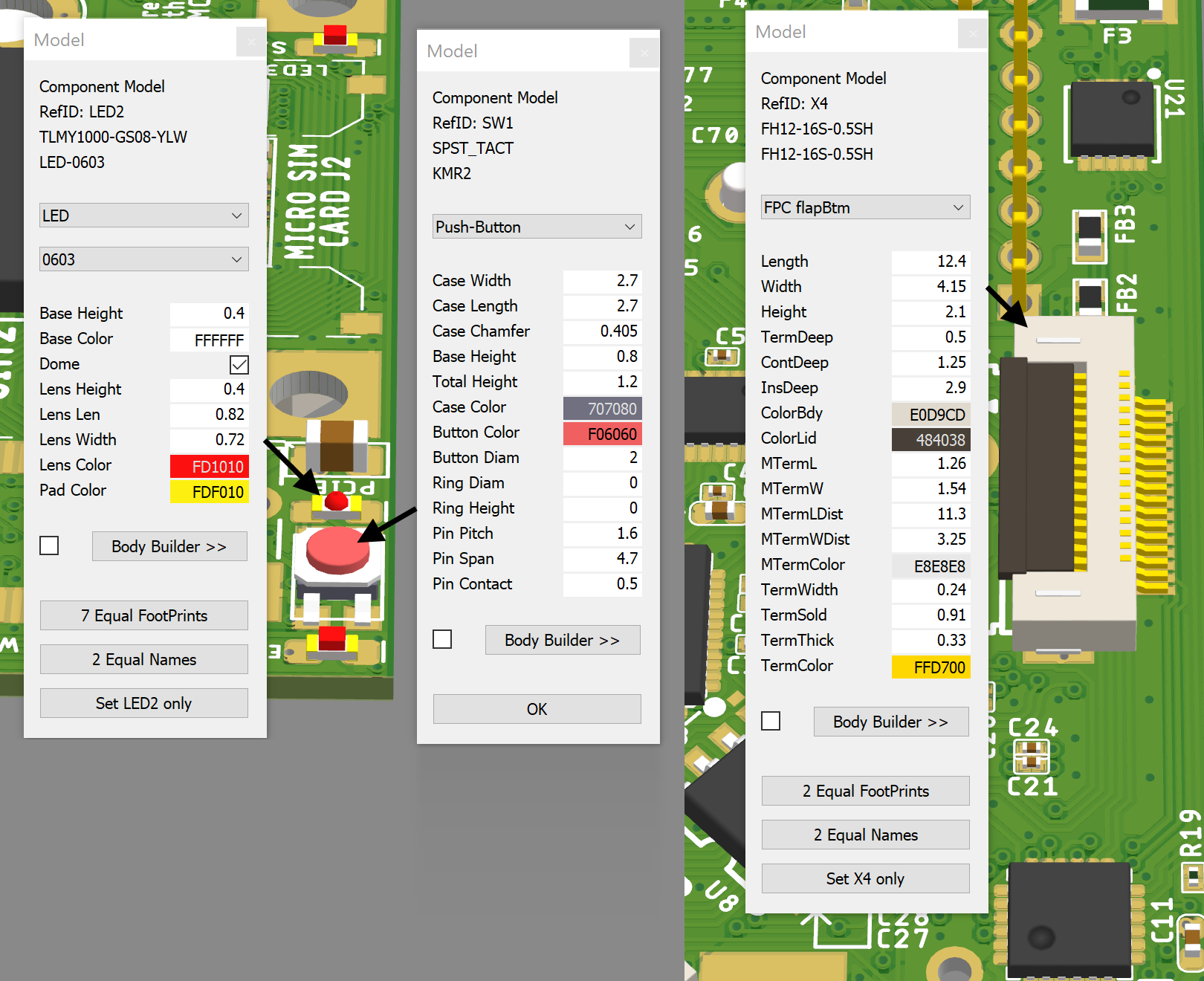
For the mechanically featured components, like switches or connectors, a simple component editor is provided.
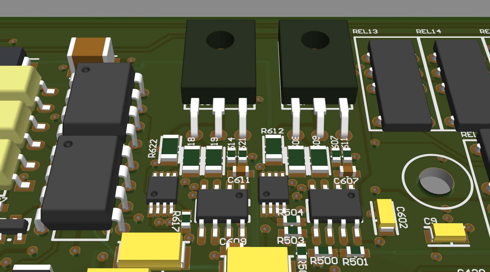
What can go wrong?
Besides typical non-compliance, like the wrong scale, wrong offset, longer names on fixed-length fields, there are conceptual problems of using IPC-356 as a netlist and for the footprint geometry:
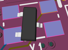
- Not connected pads may be not listed in the file. The resulting footprint will not have a complete number of pads. This is an optional setting of the CAD to CAM exporter and might be corrected if there is a possibility of regenerating the CAM files.
- THT only footprints are defined as accessible from both sides, as their pads/plated holes really are. Therefore THT components side is not directly specified. THT components are assumed to be on the top side by default.
|
Effects of not connected pad being removed from the IPC-356 file. Please check the IPC-356 generation options. |
|
 |
 |
|---|---|
Use of BOM in ZofzPCB
Bill of materials typically lists also the footprint. But it is hard to guess the case type from the footprint name. This depends very much on the library naming style. The component name or even component order number could be helpful if I used Farnell or DigiKey API. But also there, the case name from the distributor database is not consistent. So, for now, it is only used for info display, search, and changing multiple components, at once.
Note that there is an automatic column detection in the BOM file loader. It accepts formats where each component type is listed only once in the BOM and formats where each component has its own text line. BOM columns auto-detection uses statistics, and there are conditions, like a very short list, when it does not work correctly.
Overriding automatic model selection
I am trying my best to write the automatic selection algorithm, but there will surely be a need to correct its results. Additionally, there still is a need to clear the top-bottom side ambivalence of the IPC-356 file. Components model and parameter values can be adjusted either by component search dialog or by the right-click menu. The selected options are saved in the .camset and in the .zofzproj file for your convenience.
Gerber Files Set
As some IPC-356 files do not keep standard scale, I also need a Gerber file companion, along with IPC-356, because of automatic scale check/adjustment. If there are THT components, drill file would be also needed, since some IPC-356 files do not express the drill diameter correctly. The Gerber file must use "flash" commands for, at least, some percentage of the pads, to match it with IPC-356 testpoints and drills. The same matching procedure is needed for the drill file, because of the same frequent neglecting of the excellon standard scale rules. At the moment viewing the IPC-356 alone is not advised.
Why not the pick and place file?
P&P file contains only centres and sometimes pin "1" position for each component. There is no information on the pin out geometry, except a usually cryptically composed and non standard footprint name. Therefore, an excessive library of components would be needed, to reconstruct the footprints and 3D component models. The assignment and position correction procedure would be annoying and time consuming. On the other hand, as mentioned above, IPC-356 contains pinout geometry for each component. This allows me to create ad hoc 3D representation, in a simple (extruded) or elaborated way, by using more abstract software components models.
Body Builder (Premium)
The Body Builder lets you manually construct a component body out of primitives generally used by the Components Modeler. The functionality does not extend yet to the construction of the pin; you need to use one of the options from the Components Modeler. It is possible to use the clipboard to move the construction between projects. The resulting model data is tiny, and it is packed into a small text paragraph, saved in the project setup file (.camset). It is possible to manage the 'library' by using a standard text editor.
Please see the time-lapse video - constructing a DB-9 connector: